CytoFLEX Platform Flow Cytometers with IR Laser Configurations: Considerations for Red Emitting Dyes
Objectives
- Learn how to configure the CytoFLEX LX flow cytometer to optimize detection of red emitting dyes
- Understand detection characteristics for red emitting dyes with the IR laser enabled and disabled
- Step-by-step instructions for creating a detector configuration in CytExpert software
Introduction
The CytoFLEX Platform is the first flow cytometer offering an IR laser option as a standard product option. Off the shelf configurations range from two active lasers and four active fluorescence channels in the CytoFLEX and CytoFLEX S models to six active lasers and 21 active fluorescence channels in the CytoFLEX LX models. Each instrument includes the full complement of repositionable bandpass filters, regardless of the active configuration. Additional standard and non-standard bandpass filters are available for even more application flexibility. Furthermore, custom filters can be created by ordering the optical glass cut to size and mounting into a Custom Optical Filter Holder (Part Number C30171) using the Custom Optical Filter Mounting Fixture (Part Number C30249).
NOTE: Refer to CytoFLEX Platform Instructions for Use (Part Number BP49006) Appendix E Custom Optical Filter Holders for detailed guidance for creating custom optical filters.
The fluorochromes commonly used for flow cytometry applications with emission maxima of 780 nm are BV786, PE-Cy7 and APC-Alexa Fluor 750. These fluorochromes are usually detected using a 780/60 bandpass filter. The CytoFLEX Platform IR laser emits light in a narrow band of wavelengths around 808 nm. The laser excitation line at 808 nm in combination with a bandpass of 750 to 810 nm results in laser light contribution to the total light that is delivered to the detector, see figure 2. To avoid this contribution of the 808 nm laser light into the BV786, PE-Cy7 and APC-Alexa Fluor 750 detectors, a 763/43 filter was chosen for these channels, see figure 1. However, when the IR laser is not in use, a 780/60 filter is a better choice for maximizing signal collection for these fluorochromes, see figure 3. Because of the uniquely designed bandpass only optics of the CytoFLEX Platform, exchanging filters is a simple process Therefore, it’s simple to replace the bandpass filters without having to make any other filter changes.
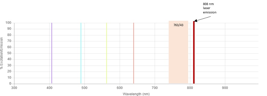
Figure 1. CytoFLEX LX Lasers and 763/43 Bandpass. The relative position of the Infrared 808 nm laser line to the 763/43 bandpass filter is shown.
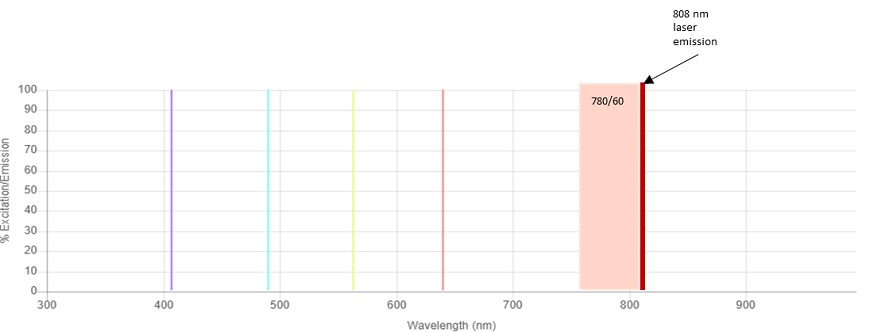
Figure 2. CytoFLEX LX Lasers and 780/60 Bandpass. The relative position of the Infrared 808 nm laser line to the 780/60 bandpass filter is shown.
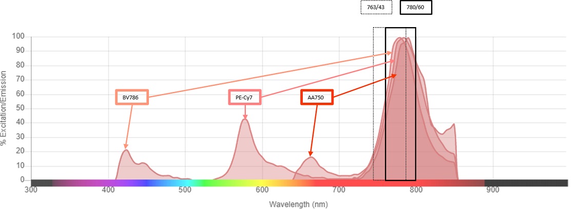
Figure 3. Emission Spectra and Bandpass Overlay. The emission spectra of BV786, PC7 and APC-Alexa Fluor 750 with both the 764/43 and 780/60 bandpass filters are shown.
CytExpert Detector Configuration Change
NOTE: Refer to CytoFLEX Platform Instructions for Use (Part Number BP49006) Chapter 7 Compensation for guidance regarding considerations for compensation and use of the compensation library.
1. Swap the filters
Open the lid of the CytoFLEX LX Flow Cytometer. Locate the Violet, Yellow Green and Red WDMs. Locate the spare filter rack in the right front corner of the instrument. Move the 763/43 from position 6 of the Violet WDM to an empty spot on the spare filter rack. Move the 763/43 from position 3 of the Yellow Green WDM to an empty spot on the spare filter rack. Move the 763/43 from position 2 of the Red WDM to an empty spot on the spare filter rack. Insert a 780/60 into the vacated position of each WDM.
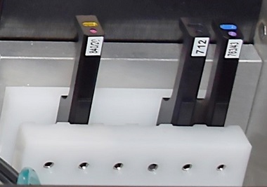
Figure 4. Spare Filter Rack. Each instrument has a built-in spare filter rack. This rack securely stores extra bandpass filters when not in use.
2. Create a new detector configuration
CytExpert uses the Current Detector Configuration to name the channels available in the experiment. The Current Detector Configuration can be found by selecting Detector Configuration from the Cytometer drop-down menu.
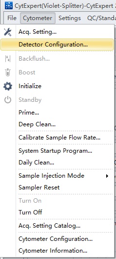
Figure 5. CytExpert Cytometer drop-down menu and Detector Configuration option.
The simplest way to create a new detector configuration is by modifying one already stored in the software. With a configuration selected, click on Save As… and provide a name. This will make a copy of the configuration. Next click on Edit… and then Filter…. Click on Add then enter "780" into the Wavelength column and "60" into the Bandpass column. Then click OK. The new filter will be listed in the Filter list. Click and drag the 780/60 filter into the position where this filter has been physically positioned.
Create a new Fluorescence by clicking on Fluorescence… and Add. Enter a name for the new channel, for example for the 780/60 filter on the Red WDM, enter the name "R780" into the Fluorescence column and "780" into the Wavelength column. The new Fluorescence will appear in the list of available Fluorescence. Click and drag on R780 in the Fluorescence list and drag it into position. Repeat for any other filter position that has been changed, then click OK.
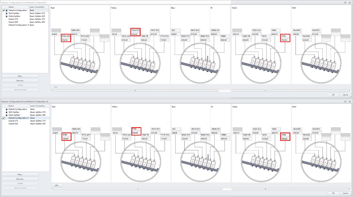
Figure 6. Detector Configuration Show Red Dye Positions. Detector Configuration showing the BV786, PC7 and AA750 WDM positions used in the Default CytoFLEX LX Detector Configuration.
3. Disable the IR laser
In the Advanced pull-down menu, select Laser Setting.
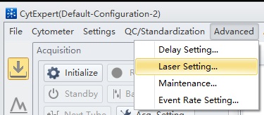
Figure 7. CytExpert pull-down menu showing the Laser Setting selection.
In the default Laser Setting all lasers are Enabled.
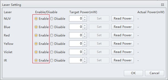
Figure 8. CytExpert Laser Setting Window. Laser setting window showing all lasers enabled.
Click on the Disable radio button for the IR laser.
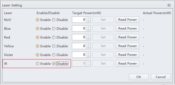
Figure 9. CytExpert Laser Setting Window with IR Laser Disabled.
Click OK and acknowledge the alerts. Proceed with creating the experiment.
Results
In order to demonstrate how the stain index varies with the filter and laser combination, anti-CD4 labelled with BV785, PC7 or APC-Alexa Fluor 750 was used to label ClearLLab Control Cells Normal. This measurement is relatively the same regardless of whether the IR laser is enabled or disabled when the 763/43 filter is installed. When the 780/60 filter is installed, there is a significant reduction in the stain index when the IR laser is enabled, however if the IR laser is disabled, an increase in the stain index is observed, see figure 10 and 11.
Therefore, if the IR laser is not needed for the experimental conditions and fluorochromes with emission maximum of 780 are in use, the IR laser should be disabled, and a 780/60 filter should be used.
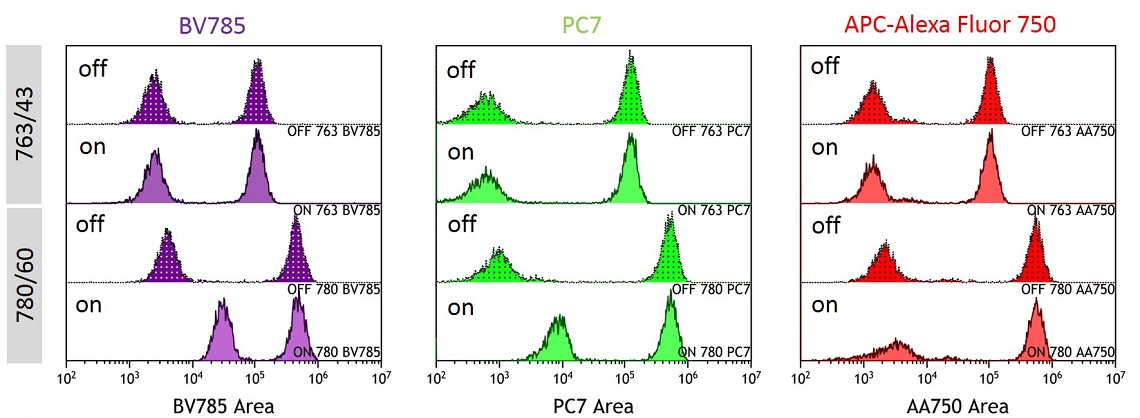
Figure 10. Overlay showing BV785, PC7 and APC-Alexa Fluor 750 Detection by Condition. BV785, PC7 and APC-Alexa Fluor 750 labelled anti-CD4 stained ClearLLab Control. Data was collected with IR laser ON or OFF with the 763/43 or 780/60 filter in position.
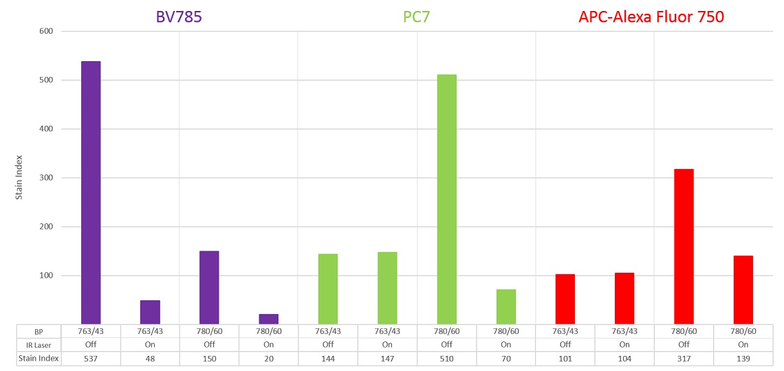
Figure 11. BV785, PC7 and APC-Alexa Fluor 750 Stain Index by Detection Condition. Stain Index was calculated for each fluorochrome and laser-filter condition.
Conclusions
The CytoFLEX Platform includes UV to IR lasers This results in allowing excitation of practically any commercially available fluorochrome. The detection can be tuned depending on the emission of the fluorochrome and balanced with other fluorochromes being used in the experiment.
The CytoFLEX WDM design makes it simple to exchange filters allowing investigators to optimize for experimentally defined needs. When the IR laser is in use, the filters for fluorochromes emitting 800 nm wavelength light can be detected by shifting the filter; however, this will diminish the amount of light captured. This can be balanced by detecting marker-fluorochrome combinations for abundantly expressed proteins in these channels If the IR laser is not in use, the filter can be exchanged for a filter aimed at the peak of the fluorochrome emission. Additionally, when the IR laser is not in use, the two channels can be used to enable additional channels for UV or Violet excitable fluorochromes by installing the CytoFLEX LX WDM Beam Splitter. Therefore, the CytoFLEX LX provides a broad range of laser excitation and options for panel design that can easily be accommodated by customizing the filters used in the detector configuration.
